How to Create a Polynesian/Gambrel Roof Truss
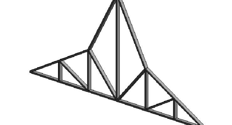
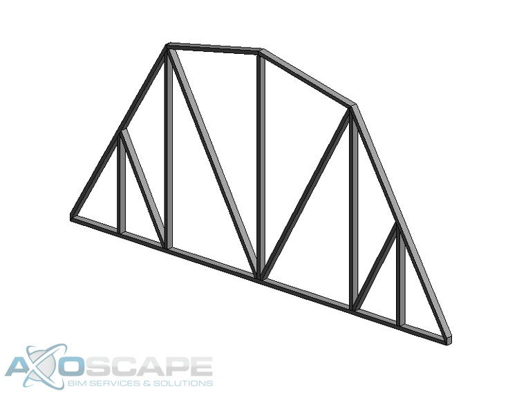
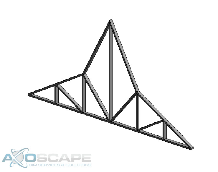
When creating this type of family you can make both a Polynesian and a Gambrel roof truss with this one model. It can be tricky to create this family, but in the end, it could save you time once this family is finished.
⦁ Open up Revit and create a new Structural Framing – Complex and Trusses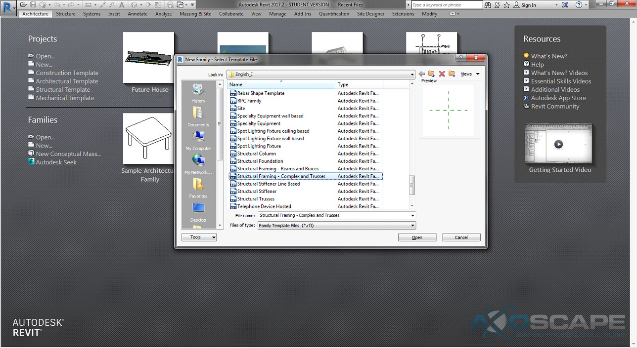
⦁ Open up the front elevation and hide the level in visual graphic (VG).
⦁ Create three vertical Reference plans on each side of the center axis. 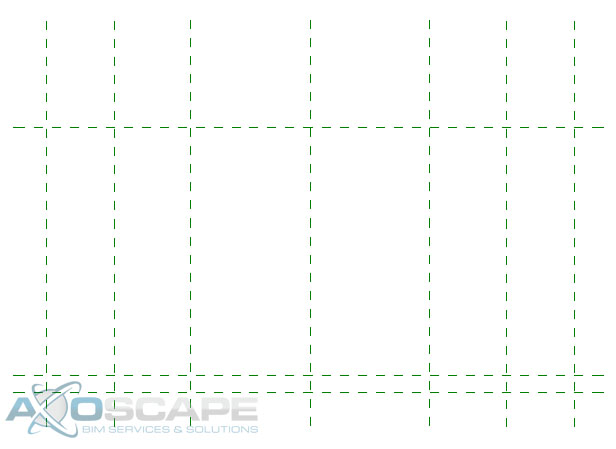
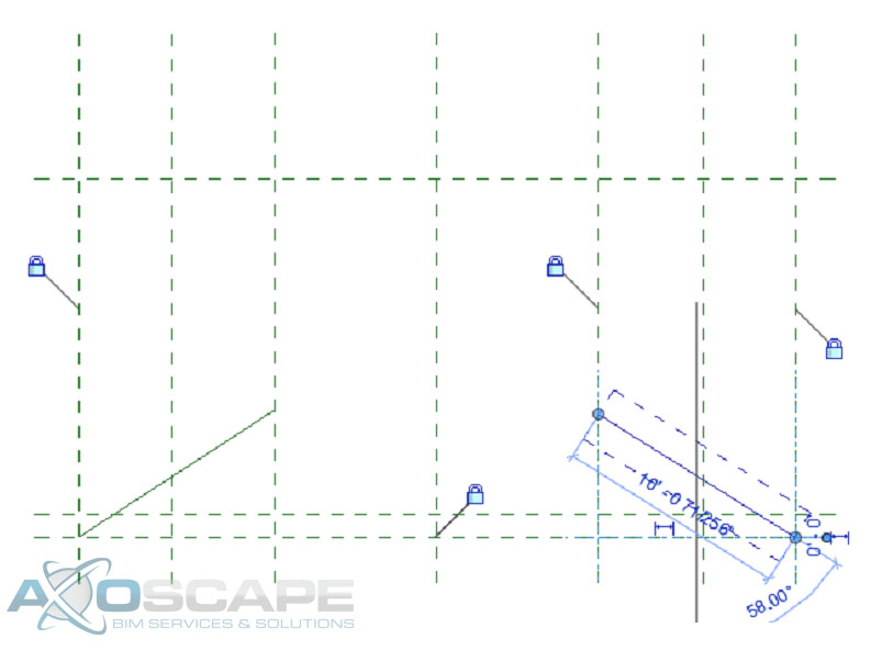
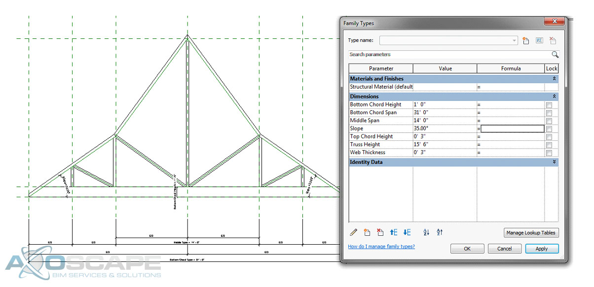
⦁ Create two diagonal reference lines to create the slope of the top chord of the truss.
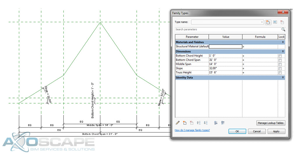
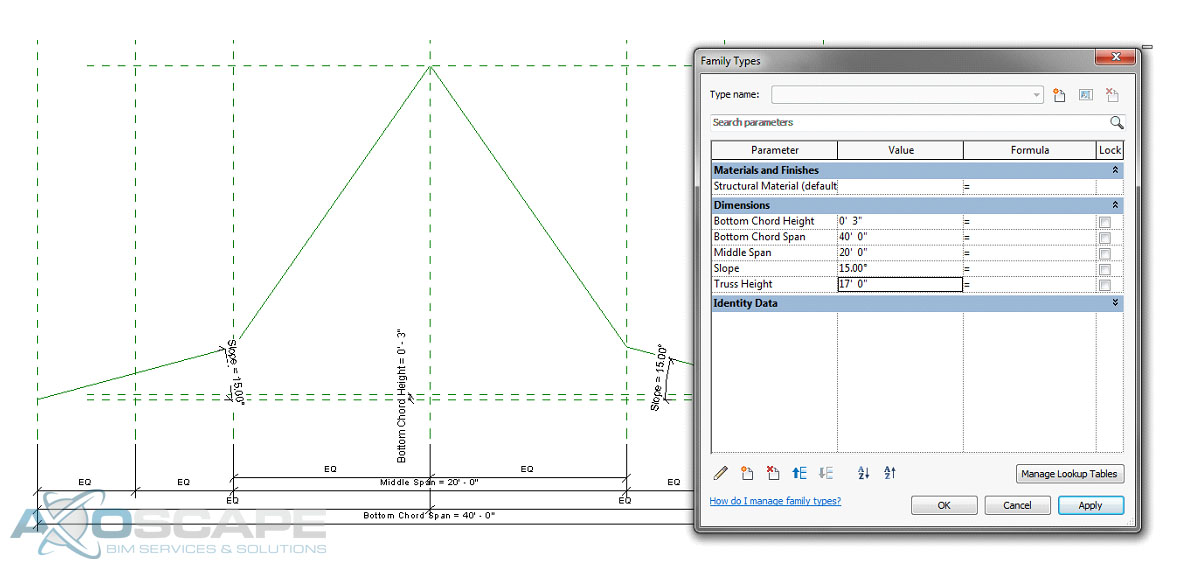
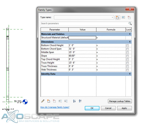
⦁ Add a dimension parameter for the bottom chord span and lock the parameter then equal space between the overhangs with a dimension.
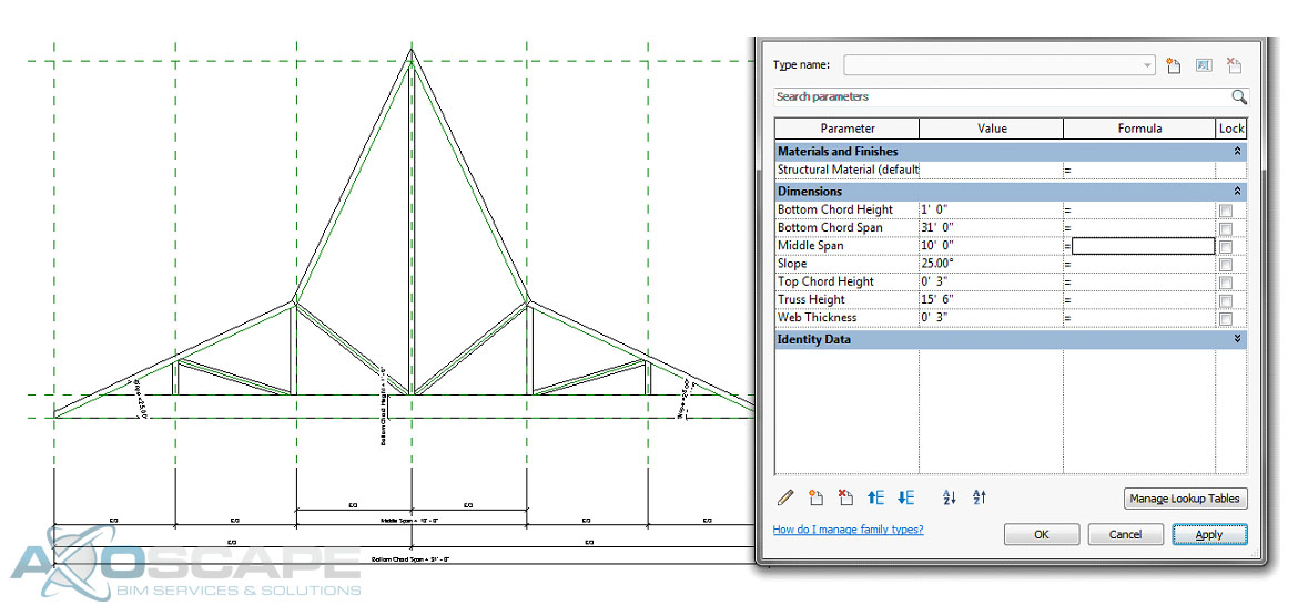
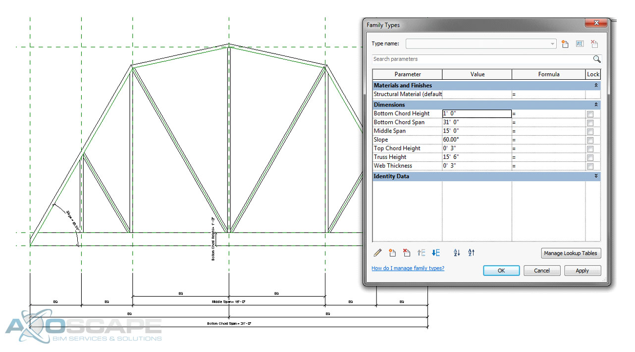
⦁ Add a dimension parameter for the middle span and lock it, then test to see if reference planes change.
⦁ Add an angle dimension parameter to each slope and lock it.
⦁ Add a reference plan for the top of the bottom chord and add a dimension parameter for the height of the bottom chord.
⦁ Add a reference plane at the top of the truss and add a dimension parameter for the truss height.
⦁ Test to make sure things are working correctly.
⦁ Using the extrusion tool create the bottom chord span by using the pick lines and trimming to get the shape, also lock the lines to the reference planes.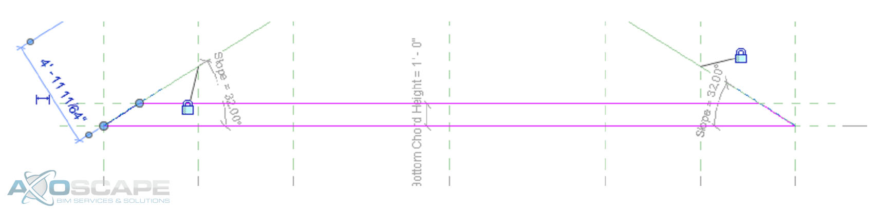
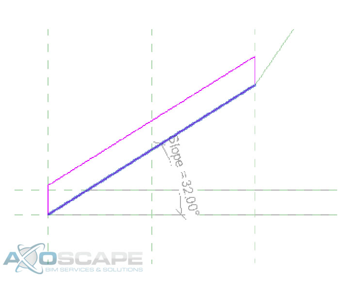
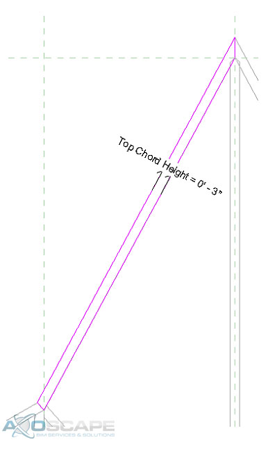
⦁ Do the same thing to create the top chords for each side, also add a dimension to control the height of the top chord and make sure you lock it to the reference line.
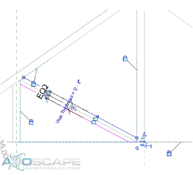
 ⦁ Extrude the webs on each side by using the two vertical reference planes on each side, also add a dimension parameter for the web thickness.
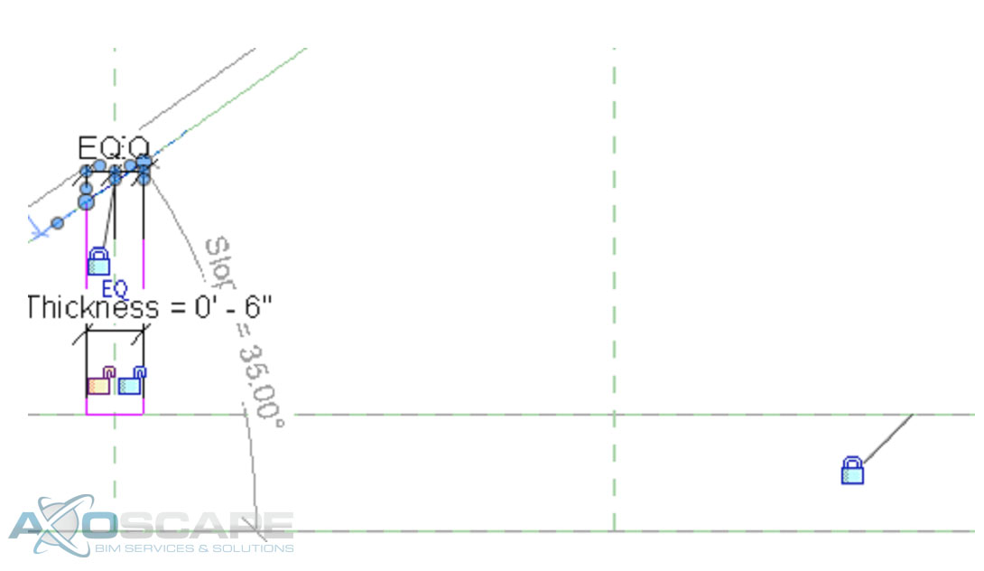
 ⦁ Use the extrude tool make middle web member the same way.
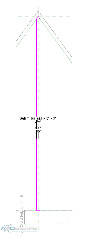 ⦁ Test to make sure things are working correctly.
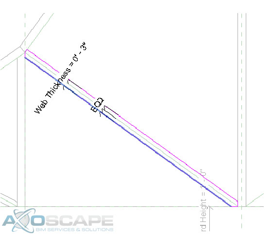
⦁ Add reference lines for the webs to each side and lock it to the top and bottom chords. Then test for function.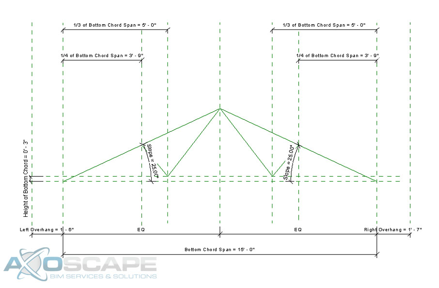 ⦁ Use the extrusion tool to create the web of the truss in two separate pieces. Center the web around the reference line and dimension the width of the web.
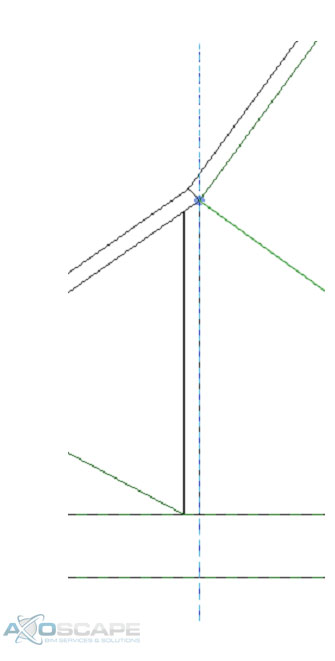
 ⦁ Test to make sure everything works accordingly.
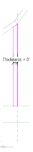
 ⦁ Open up the left elevation and create a reference plane for the thickness of the truss and align extrusions to the reference plane. Then test to make sure everything works like its suppose to.
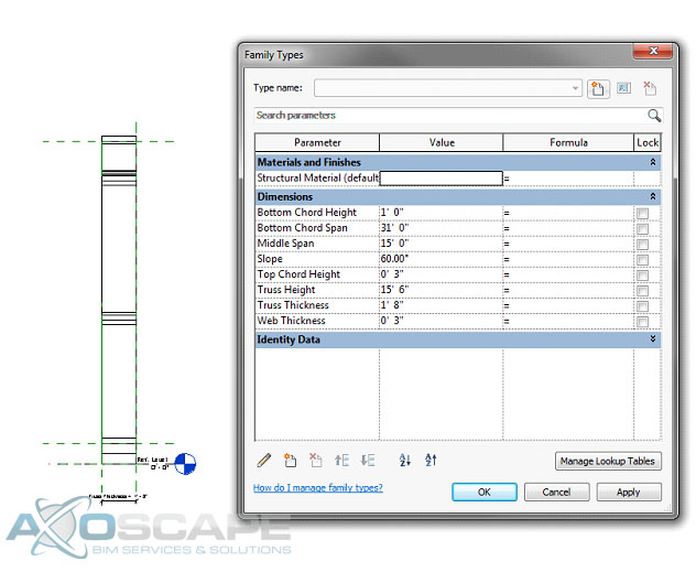


