Archives for Jan,2018

You are browsing the site archives by date.

How to Add Rowlock Brick Sill to Window Family

When creating rowlocks bricks underneath windows, it is tempting to simply draw in sweeps and call it a day.  The problem with this technique is, if window moved or changes shape, those sweeps will not update which will require manual intervention. Instead, the better way of creating rowlock bricks at the window sill is within the window family. By building the rowlocks in with the windows, the rowlock will update automatically. 

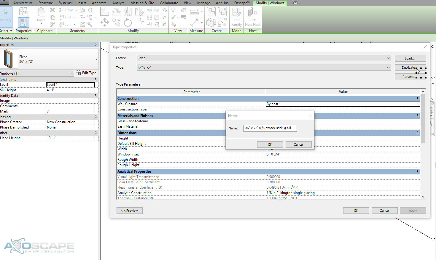
  1. Select the window in the project to begin.

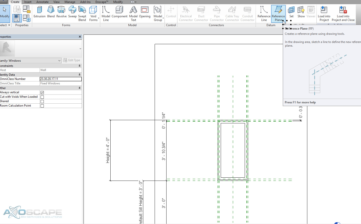
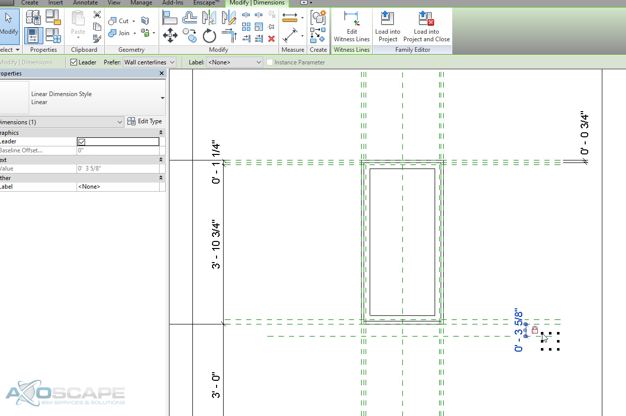
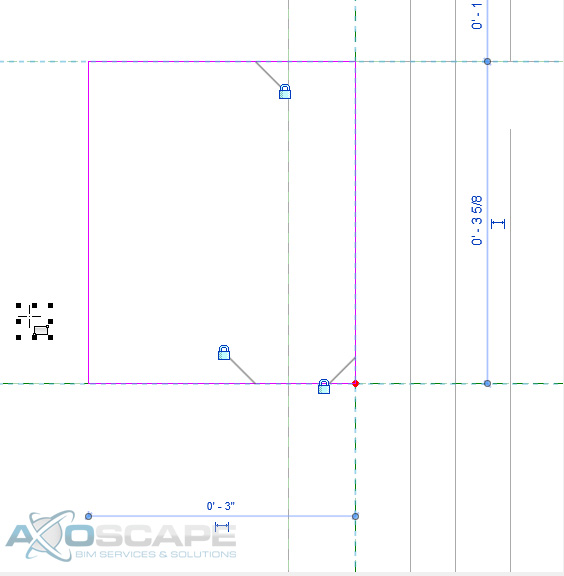
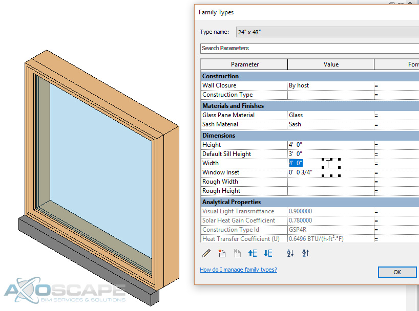
  1. Click edit family to edit the window family. Go to Elevations Exterior view and draw a new reference plane 3-5/8” away from the sill for the depth of the brick. Lock the Reference Plane.

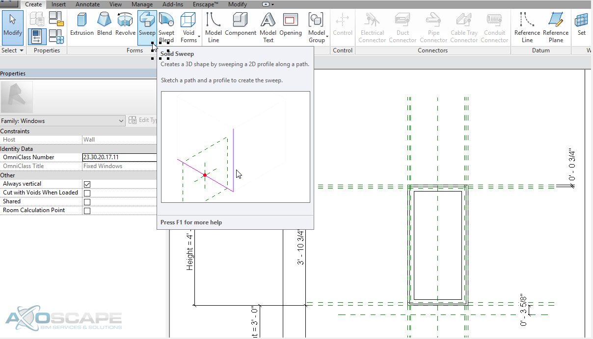
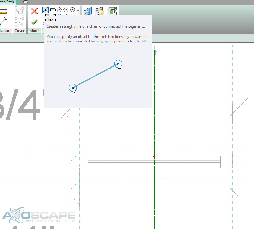
  1. In the create tab select Sweep and sketch the path of the rowlock.

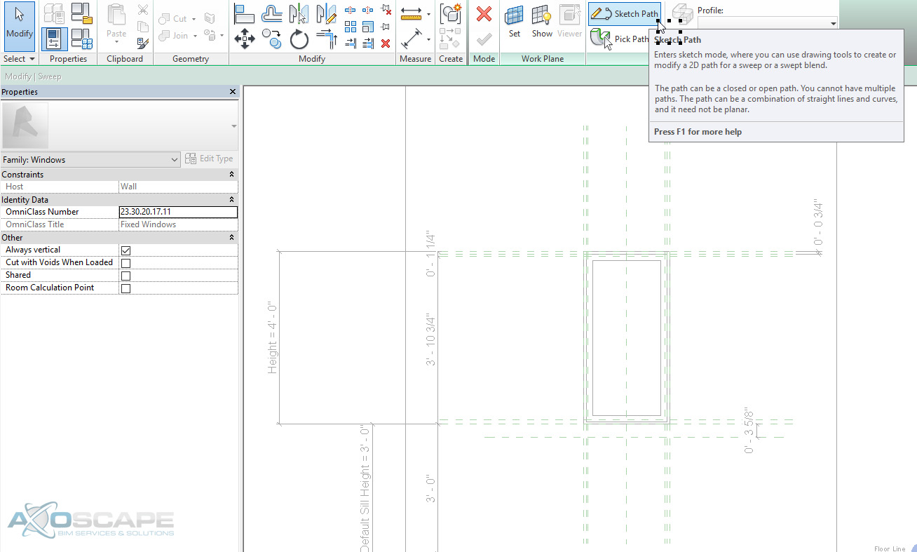
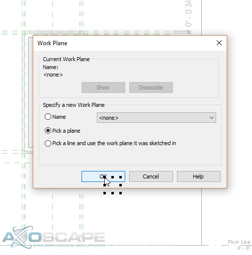
  1. But before drawing the path the work plane will need to be picked to draw off of. In this case, pick the new reference plane that was created.    

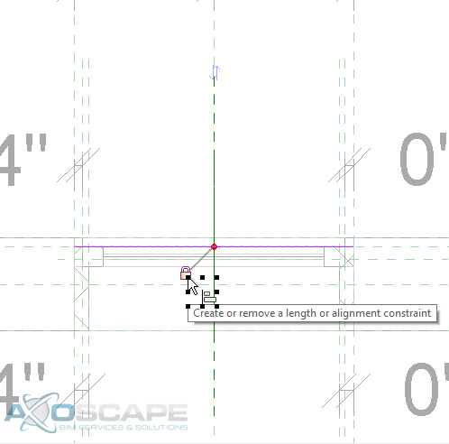
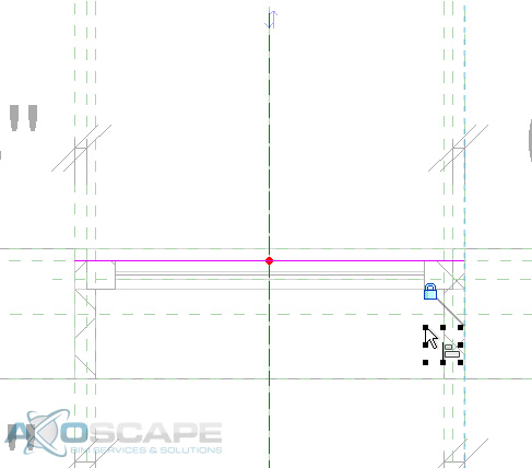
  2. Sketch a line and lock the line to the reference planes that encompass the window frame. Click Finish Edit Mode once done.

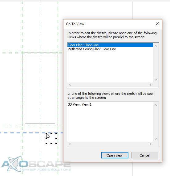
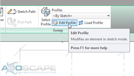
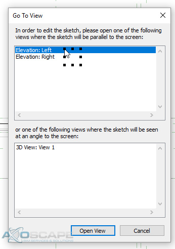
  3. Click “Edit Profile” under “Profile” to draw the profile of the rowlock brick. Go to the “Left Elevation” view to sketch the profile.

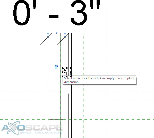
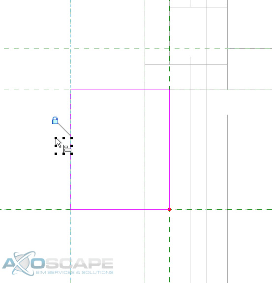
  4. Draw the brick sill to the preferred dimension and lock the profile to the reference plane. Draw another reference plane and lock the new reference plane to the inside face of window’s reference plane. Go back to the sweep and lock the last face to the reference plan.


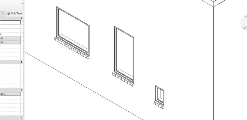
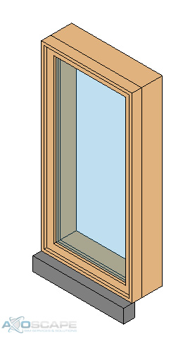
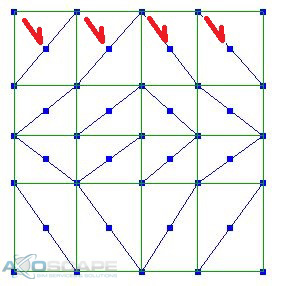
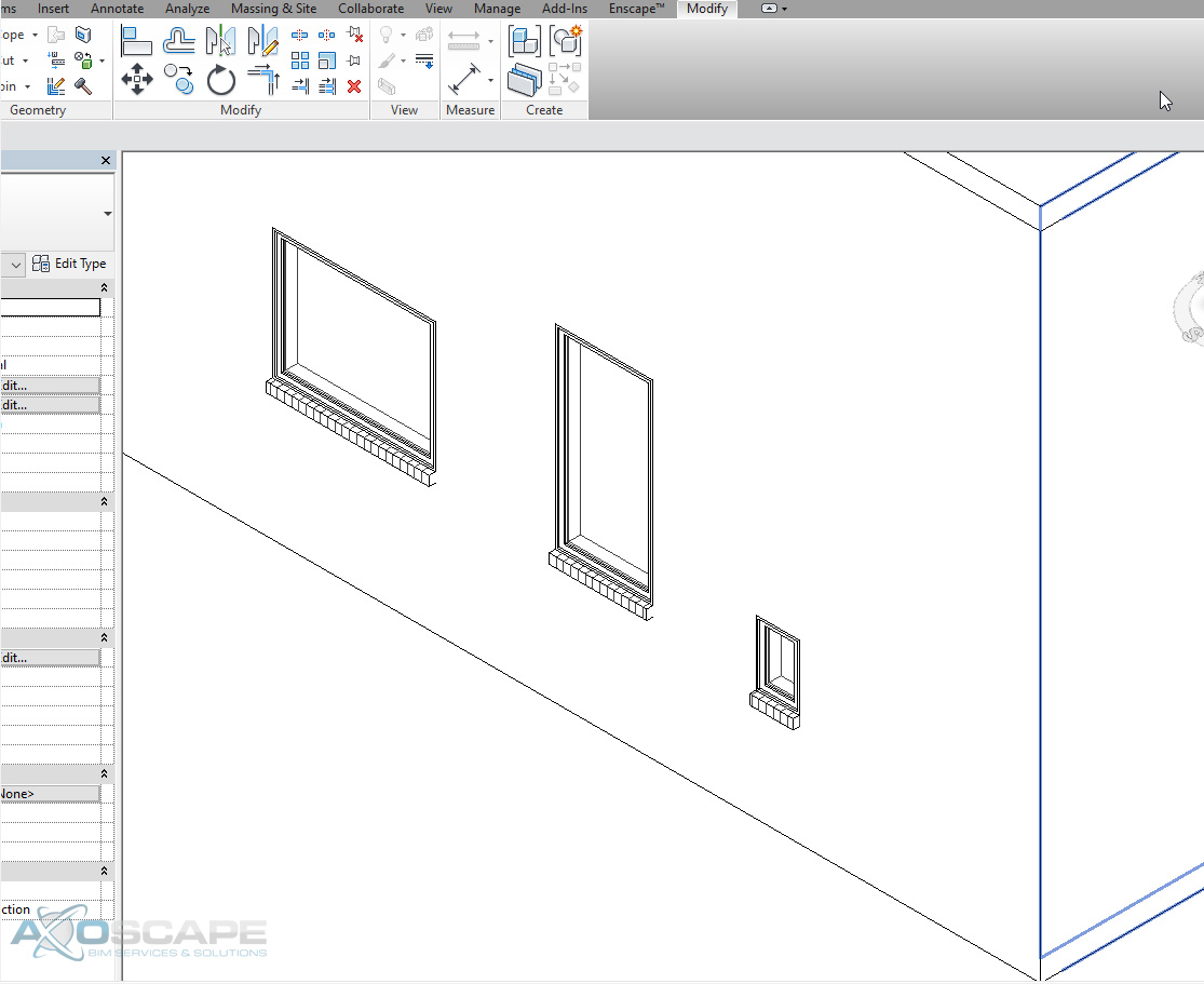
  5. To test if the rowlock works correctly, go into a 3D View and it should show the brick sill. The brick sill should stretch with the width of the window.

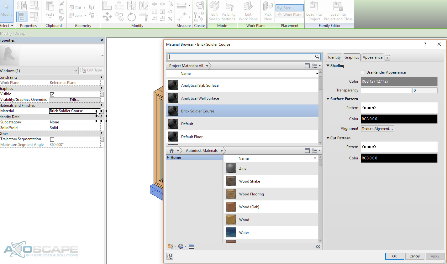
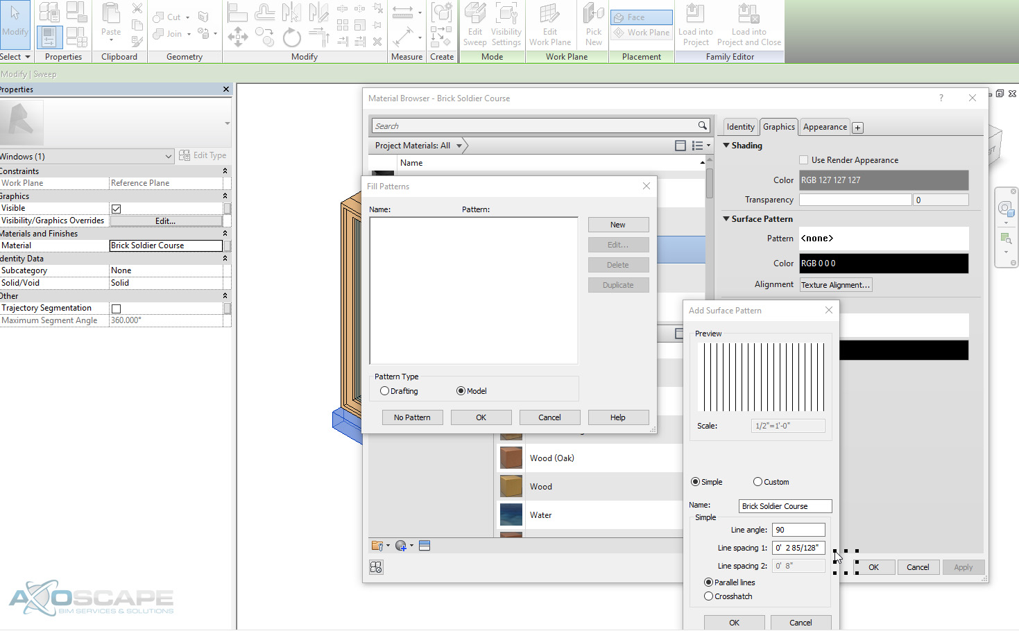
  6. Change the material of the rowlock by clicking Material to open the Material Browser. Create a new material and call it Brick Soldier Course. In the “Surface Pattern” area in the graphics tab, click on “surface pattern”. Click Model and New to bring up the Add Surface Pattern. Rename the pattern, change the line angle to 90 degrees, change line spacing 1 to 2- 85/128” and hit OK to get out of the Material Browser.

  7. The final result after reloading the window family into the project. 

Congratulations! Now the brick rowlocks update dynamically. This method requires a bit of work to setup, but will undoubtedly save much more time down the road.

Read More

How to Batch Download RVT Models from UNIFI

UNIFI just improved the tool for batch downloading RVT models, today!
In addition to the steps to batch download, we will use “Bulk Rename Utility” to move the RVT files from the UNIFI download directory to a different folder.

Let’s start!

The next window works for .rfa files. It will not download the files in the version selected, but the base version.

Save the zip files to the desired directory.

Extract the zip files.

The image below shows UNIFI’s folder structure for Batch Downloading files.

Now, let’s use Bulk Rename Utility dig in the previous directory and move only the RVT files to a new location.

Finally, we are done!

Note: UNIFI is working on giving us more options to download our data!

Read More

Scheduling Beam Connections Using Shared Parameters

This workflow was created from a project for RM Rodgers, Inc., a subcontractor who specializes in wood beam systems with over 50 years of experience. This was one of the first projects where 3D modeling was required for coordination purposes. This article will cover how to schedule out beam connection components. Here’s a look at the schedule.


This schedule needs to reflect the everchanging conditions of the project and update dynamically. For example, if an existing connection is altered, the bolt counts and other parts change. In addition to the connection changes, the elevation sheets and B.O.M schedule must be updated.

This is your typical workflow when it comes to producing cut sheets for any manufacturer.


Manually updating every sheet in the project is tedious and time-consuming.  To avoid this manual rework, a shared parameter will provide automation. 

  1. Create family parameters for each connection in the Other category (Structural Stiffener category).
  2. Create shared parameters required for each family.
  3. Generate structural stiffener schedules for the connections.

Once you have all this information preloaded in the connection families, updates to scheduling are automated. Making it simple for the user to keep accurate counts on every component dynamically.

Read More

Workflow to Set Default 3D View for BIM 360 Team

The problem
Currently, it is only possible to control views and sheets to be published to BIM 360 Team. However, there is no way to set a 3D view as default when opening the model in BIM 360 Team. For example, in the “rac_basic_sample_project.rvt”, there are seven (7) 3D views that I selected to publish to BIM 360 Team using the tool Publish Settings in Revit (See Image below).

In this case, the default 3D in BIM 360 Team was “Kitchen” (See image below).

Background analysis
After testing on a couple of Revit files on how BIM 360 Team determines which 3D view to be set as default for the web viewer, I inferred that BIM 360 is selecting the default 3D view based on the element Id, the 3D view with the lowest Id number or the oldest view because Revit always increments the Ids before assigning them to new elements. Read more about element Ids from Jeremy’s post.

To confirm this hypothesis, a Dynamo script collected the element Ids and the 3D view names. The kitchen view has the lowest Id number from the list. See image below.

Approach to the problem
Knowing the above, the idea is to identify the 3D view we want to set as default and duplicate the rest of them so, its element Ids increment. Using Dynamo, these are the steps followed to set a new default 3d view for BIM 360 Team.

  1. Collect 3D view from model
  2. Filter the “future default 3D view”
  3. Set a new name for the rest of the 3D views only if its element Id is less than the “future default 3D view” element Id number (to avoid duplicating unnecessary elements)
  4. Rename the views that its Id numbers were less than the “future default 3D view” using a special string to further identify and remove it
  5. Duplicate the renamed views
  6. Delete renamed views
  7. Remove the special string from the name of the duplicated views
  8. Update Sheet Set including duplicated views then check publish settings
  9. Reupload the Revit model to BIM 360 Team


Download this Dynamo Script!


Disclaimer
This approach is not considering if there is a 3D view placed on a sheet. If that is the case, the 3D view will be removed from the sheet. Run in manual mode.

Results
BIM 360 Team default view was updated.

Read More

Getting Center Points of a Model or Detail Line Grid

This article comes from a question in the Dynamo Forum on how to calculate the center point of each square in a grid pattern.  

The solution is to get intersection points of the grid and triangulate them as a topo mesh. Thus, collecting the inclined curves and its mid-points. See image below.

There are a couple of python scripts in the graph to facilitate list management. Download the script here:

Or take a look at the dynamo script to adapt it to your needs.

Feel free to comment if you have any questions!

Read More